NIKIMAT


Amel Super Maramu 2000
|
Lofrans Tigres Windlass Overhaul Part 1: 10 Pictures from 01 to 7 Preparation, removing the cover of the electric motor, disconnecting the wires |
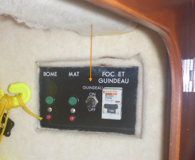
Picture 01
In addition to have the "Instrument" off on the 24 Volt panel
I switch Off the windlass breaker "Guindeau" (Orange arrow) in the forward cabin (forward closet, port side)
My main reason to this was to avoid an accidental short:
as you will see in picture 22, all the wires wrap together in a plastic bag
I was afraid I would need to switch on the Instrument" and that the wires of the switched commanding the windlass would touch
Then turn on the solenoids and then short the large electric wires powering the windlass
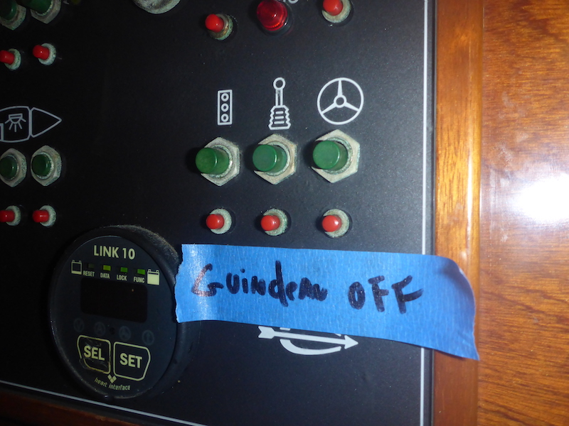
Picture 02
Since I rarely switch off the Windlass (Guindeau) breaker, I put a reminder on the 24 Volt panel
Picture 03
Here is a picture of all the spares parts I have for the windlass

Picture 1
Disconnect the chain from the anchor and secure it
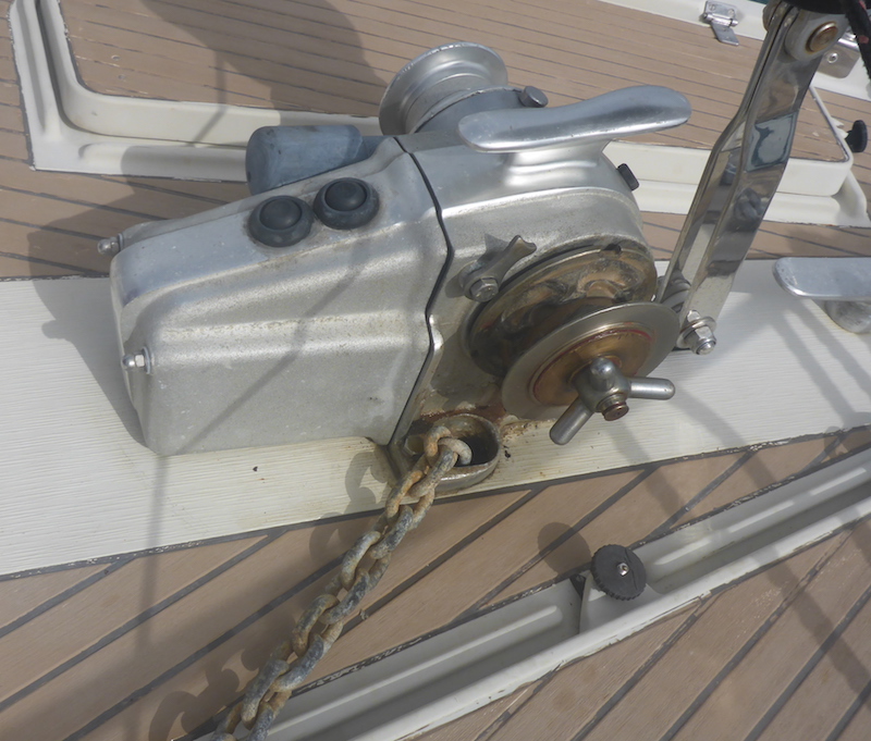
Picture 2
Unbolt the cover of the electric motor
Picture 3
plastic washer, metallic washer and bolt
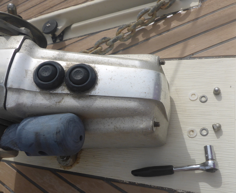
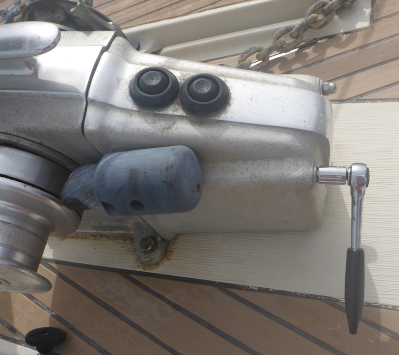
Picture 4
The cover comes out easily
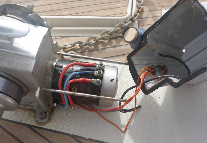
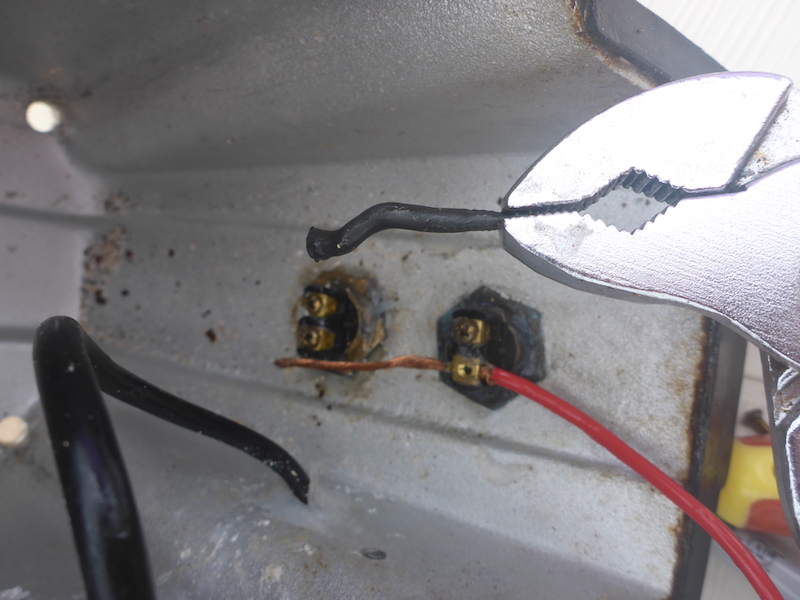
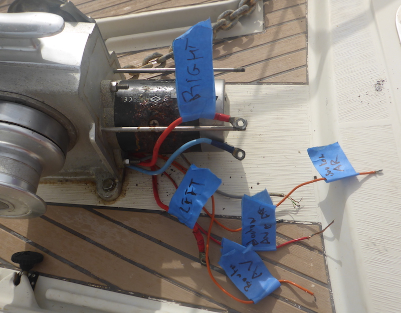
Picture 5
As you remove the electric wire, make sure to label them
Note: how the positive/Red wire goes from one switch to the other, it is strip and uses a cover in between the 2 switches
Picture 6
Write down (picture is easier) the wires of the "Eye" of the Chain Counter
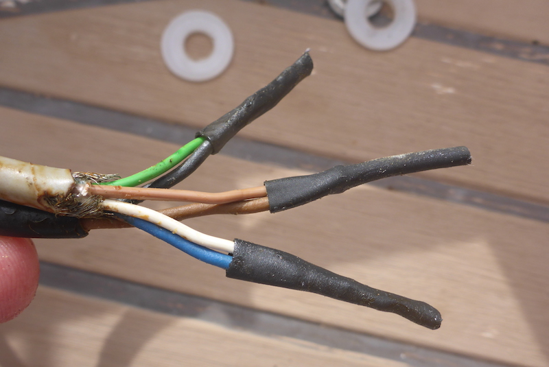
Picture 7
All labeled
|
Next: Part 2
|
|
Part 1 10 Pictures from 01 to 7
Part 2 17 Pictures from 8 to 24
Part 3 8 Pictures from 25 to 32
Part 4 15 Pictures from 26 to 40
Part 5 8 Pictures from 41 to 48
Part 6 7 Pictures from 49 to 55
Part 7 13 Pictures from 56 to 68
Part 8 5 Pictures from 69 to 73
Part 9 10 Pictures from 74 to 83
Part 10 4 Pictures from 84 to 87
Part 11 7 Pictures from 88 to 94
Part 12 6 Pictures from 95 to 100
Part 13 8 Pictures from 100 to 107
Part 14 6 Pictures from 108 to 114
Part 15 15 Pictures from 115 to 129
Part 16 16 Pictures from 130 to 145 |
Part 17 3 Pictures from 146 to 148 Putting key back on Electric motor shaft
Part 18 8 Pictures from 149 to 156
Part 19 12 Pictures from 157 to 168
Part 20 9 Pictures from 169 to 177
Part 21 16 Pictures from 178 to 193
Part 22 15 Pictures from 194 to 208
Part 23 19 Pictures from 209 to 217
Part 24 20 Pictures from 218 to 239
Part 25 5 Pictures from 240 to 244
Part 26 3 Pictures from 245 to 247
Part 27 6 Pictures from 248 to 253
Part 28 4 Pictures from 254 to 258
Part 29 7 Pictures from 259 to 266
Part 30 12 Pictures from 267 to 278
Part 31 16 Pictures from 279 to 294
Part 32 6 Pictures from 295 to 300
|